Referenced Setup
In this section, you will learn how to use the OpenFMB Adapter Config tool to create configuration files for the OpenFMB Adapter used by the Referenced Setup.
As specified in the Referenced Setup, there are four types of electrical equipment:
- Building load: meter device speaking DNP3
- Solar PV: solar system speaking MODBUS
- Battery energy storage: battery speaking MODBUS
- Switch (isolator) at PCC (Point of Common Coupling): isolate switch speaking DNP3
Work Folder
Work folder is a folder on your local computer where the Adapter configuration files are located.
Launch OpenFMB Adapter Config tool, then click on "Open Work Folder," and browse to open a folder where you will store the Adapter configuration files. For this tutorial, the selected folder name is
demo.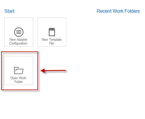
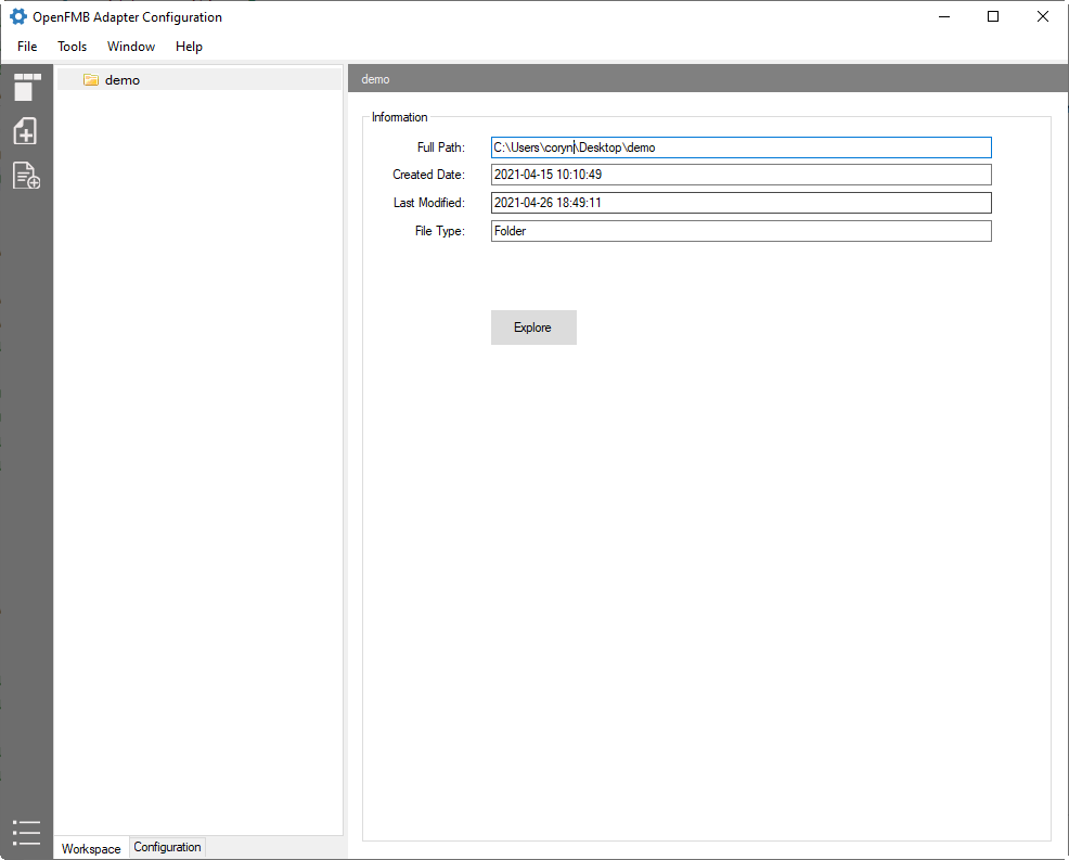
The folder is loaded.
Building Load Adapter Configuration
The meter device used for building load metering is a DNP3 device with the following simple DNP3 data points:

We use MeterReadingProfile for the building load.
First, let's create a subfolder for the building load. From the left pane, right-click on the folder named
demo, selectNew Folder, and type inbuilding.On the newly created subfolder
building, right-click, and selectNew Adapter Configuration.On
New Adapter Configurationdialog, selectdnp3-masterplugin, then checkMeterReadingProfileon the right pane. Click the OK button.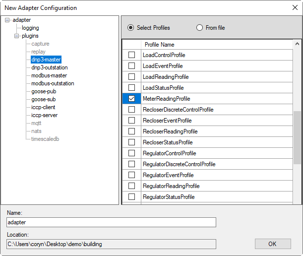
Now on the workspace tree view, you will see a structure similar to the image below. Select
adapter.yamlon the tree view, then click onEditto launch configuration editor.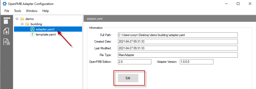
The configuration editor screen has two main panes: a left navigator pane and details pane. Familiarize yourself with the tool by clicking on each tree node of the left navigator.
:::Note
- Plug-ins node includes the supported plugins that you can choose to enable
- Protocol-related plugin can have one or more sessions associated with it.
:::
For this reference setup, you need to enable
NATSanddnp3-master. Click onpluginsnode and checkNATSanddnp3-masterTo do the protocol mapping between DNP3 and OpenFMB MeterReadingProfile, expand
dnp3-masternode, session, then selectMeterReadingProfile.- Assign MRID of the metering device to the profile by clicking on the
mRIDon top right corner, then click on...button. Enter0648ef71-cb63-4347-921a-9dbf178da687as the mRID. - Map DNP3
analog input index 0toWof thereadingMMXUin the MeterReadingProfileType
Win the search box (middle screen) to see a list of availableWdata items. SelectW total (mag)for the total power consumption (mag).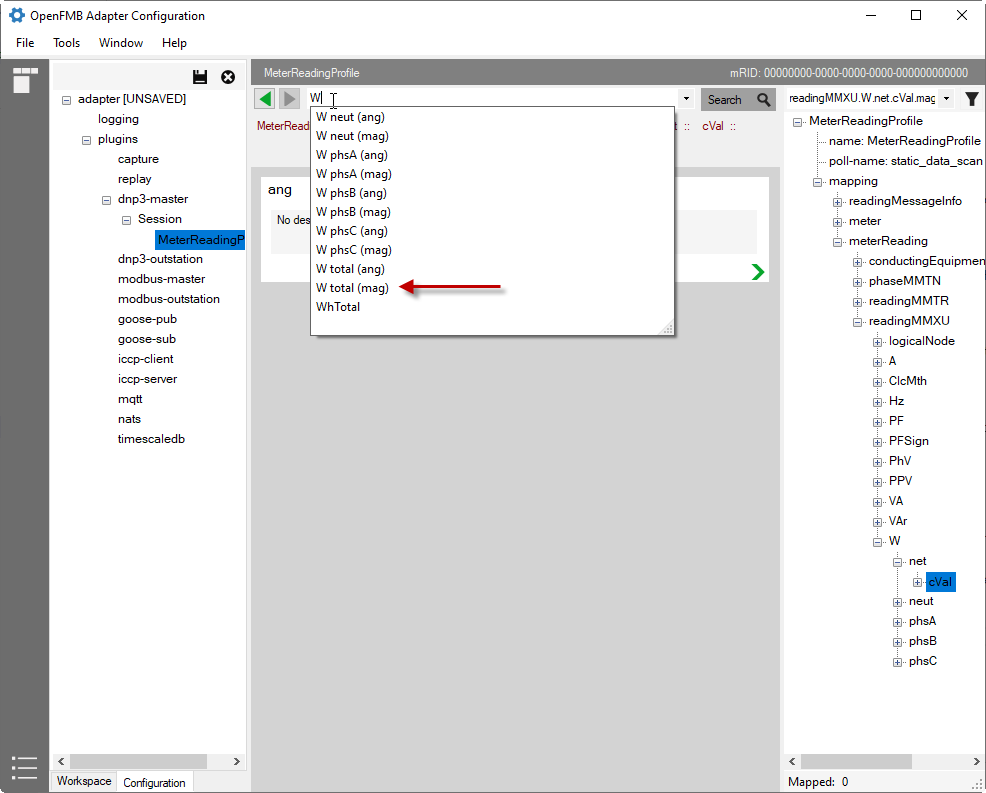
Drill down on the
magby clicking on the green arrow at the right bottom corner of themagbox.On the field type dropdown, select `mapped'.
On
Source Type, selectanalog.On
Index, enter 0On
Scale, enter 1You have completed the mapping of
Analog Input 0tometerReading.readingMMXU.W.net.cVal.magwithscale factor 1.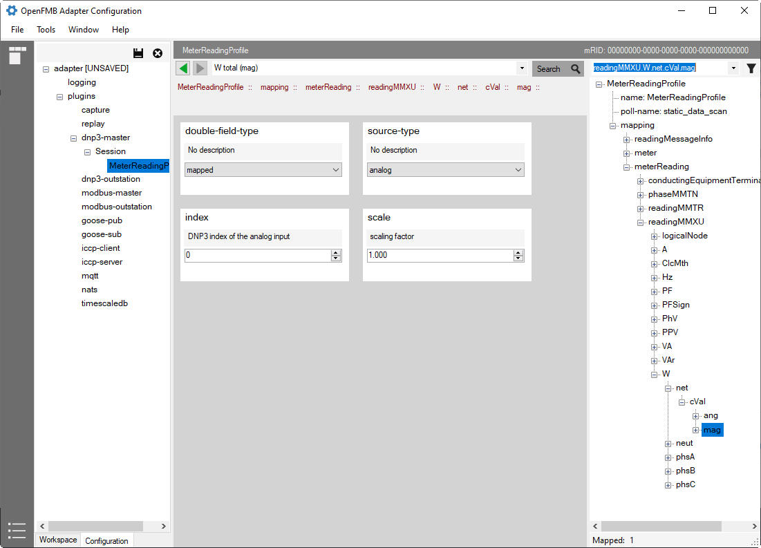
- Assign MRID of the metering device to the profile by clicking on the
Configure NATS by expanding
pluginsand select NATS.- Make sure that
enabledcheckbox is checked. - Enter NATS connection URL.
- Select
noneasSecurity Type. - Click on
Reset Subjectsto populate the publishing profiles.
- Make sure that
Save your configuration by clicking the
Savebutton or simply CTRL+S
Solar Adapter Configuration
The solar device is a MODBUS device with the following simple MODBUS data points:

We use SolarReadingProfile for the solar power production and SolarStatusProfile for state indication.
First, let's create a subfolder for the solar device. From the left pane, right-click on the folder named
demo, selectNew Folder, and type insolar.On the newly created subfolder
solar, right-click and selectNew Adapter Configuration.On
New Adapter Configurationdialog, selectmodbus-masterplugin, then checkSolarReadingProfileandSolarStatusProfileon the right pane. Click OK.Now on the workspace tree view, you will see a structure similar to the image below. Select
adapter.yamlon the tree view, then click onEditto launch configuration editor.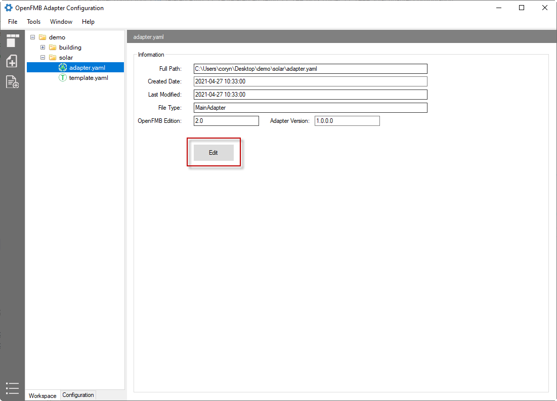
For this reference setup, you need to enable
NATSandmodbus-master. Click onpluginsnode and checkNATSandmodbus-master.To do the protocol mapping between MODBUS and OpenFMB SolarReadingProfile, expand
modbus-masternode, session, then selectSolarReadingProfile- Assign MRID of the metering device to the profile by clicking on the
mRIDon top right corner, then click on...button. Enter540b292a-e600-4ae4-b077-40b892ae6970as the mRID. - Map MODBUS
Holding Register Pair [0, 1]toWof thereadingMMXUin the SolarReadingProfileType
Win the search box (middle screen) to display a list of availableWdata items. SelectW total (mag)for the total power consumption (mag).Drill down on the
magby clicking on the green arrow at the right bottom corner of themagboxOn the field type dropdown, select `mapped'.
On
Source Type, selectholding_register.On
Register Mapping, selectuint32.On
Scale, enter 0.01On
Lower Index, enter 0On
High Index, enter 1You have completed the mapping of
Holding Register Pair [0, 1]tosolarReading.readingMMXU.W.net.cVal.magwithscale factor 0.01.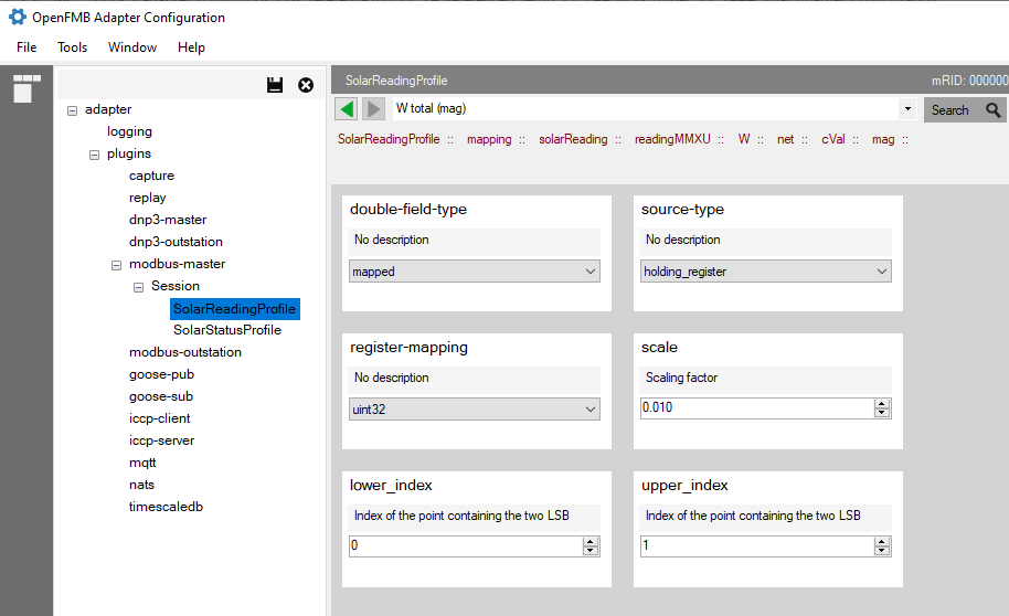
- Assign MRID of the metering device to the profile by clicking on the
To do the protocol mapping between MODBUS and OpenFMB SolarStatusProfile, expand
modbus-masternode, session, then selectSolarStatusProfile- Assign MRID of the metering device to the profile by clicking on the
mRIDon top right corner, then click on...button. Enter540b292a-e600-4ae4-b077-40b892ae6970as the mRID. - Map MODBUS
Coil 0tostateof thePointStatusin the SolarStatusProfileOn the right profile navigator tree, drill down to
statewith the following path:solarStatus -> solarStatusZGEN -> solarEventAndStatusZGEN -> PointStatus -> stateOn the field type dropdown, select `mapped'.
On
Source Type, selectcoil.On
Enum Field Type, selectsingle-bit.On
Index, enter 0On
When-True, selectStateKind_on.On
When-False, selectStateKind_off.You have completed the mapping of
Coil 0tosolarStatus.solarStatusZGEN.solarEventAndStatusZGEN.PointStatus.state.value.- when Coil 0 = true, the state value is equivalent to
StateKind_on. - when Coil 0 = false, the state value is equivalent to
StateKind_off.
- when Coil 0 = true, the state value is equivalent to
- Assign MRID of the metering device to the profile by clicking on the
Configure NATS by expanding
pluginsand select NATS.- Make sure that the
enabledcheckbox is checked. - Enter NATS connection URL.
- Select
noneasSecurity Type. - Click on
Reset Subjectsto populate the publishing profiles.
- Make sure that the
Save your configuration by clicking the
Savebutton or simply CTRL+S.
Battery Adapter Configuration
The battery is a MODBUS device with the following simple MODBUS data points:
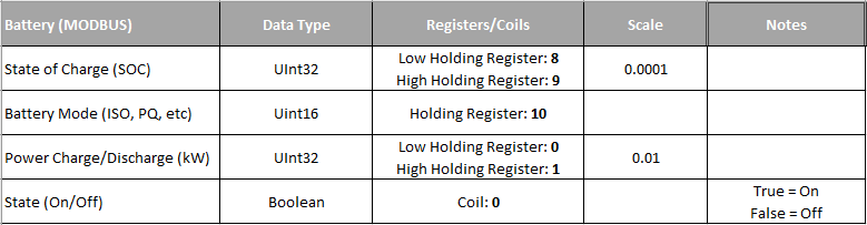
We use ESSReadingProfile for the solar power charge/discharge and ESSStatusProfile for state, state of charge, and battery mode.
First, let's create a subfolder for the battery. From left pane, right click on folder named
demo, selectNew Folderand type inbattery.On the newly created subfolder
battery, right-click, and selectNew Adapter Configuration.On
New Adapter Configurationdialog, selectmodbus-masterplugin, then checkESSReadingProfileandESSStatusProfileon the right pane. Click OK.Now on the workspace tree view, you will see a structure similar to the image below. Select
adapter.yamlon the tree view, then click onEditto launch configuration editor.For this reference setup, you need to enable
NATSandmodbus-master. Click onpluginsnode and checkNATSandmodbus-masterTo do the protocol mapping between MODBUS and OpenFMB SolarReadingProfile, expand
modbus-masternode, session, then selectESSReadingProfile- Assign MRID of the metering device to the profile by clicking on the
mRIDon top right corner, then click on...button. Enter836a8638-b448-4961-8258-47aa18e05f65as the mRID. - Map MODBUS
Holding Register Pair [0, 1]toWof thereadingMMXUin the ESSReadingProfile- Type
Win the search box (middle screen) to display a list of availableWdata items. SelectW total (mag)for the total power consumption (mag). - Drill down on the
magby clicking on the green arrow at the right bottom corner of themagbox. - On the field type dropdown, select `mapped'.
- On
Source Type, selectholding_register. - On
Register Mapping, selectuint32. - On
Scale, enter 0.01 - On
Lower Index, enter 0 - On
High Index, enter 1 - You now complete the mapping of
Holding Register Pair [0, 1]toessReading.readingMMXU.W.net.cVal.magwithscale factor 0.01.
- Type
- Assign MRID of the metering device to the profile by clicking on the
To do the protocol mapping between MODBUS and OpenFMB ESSStatusProfile, expand
modbus-masternode, session, then selectESSStatusProfile- Assign MRID of the metering device to the profile by clicking on the
mRIDon the top right corner, then click on...button. Enter836a8638-b448-4961-8258-47aa18e05f65as the mRID. - Map MODBUS
Coil 0tostateof thePointStatusin the ESSStatusProfile- On the right profile navigator tree, drill down to
statewith the following path:essStatus -> essStatusZGEN -> essEventAndStatusZGEN -> PointStatus -> state - On the field type dropdown, select `mapped'.
- On
Source Type, selectcoil. - On
Enum Field Type, selectsingle-bit. - On
Index, enter 0 - On
When-True, selectStateKind_on. - On
When-False, selectStateKind_off - You now complete the mapping of
Coil 0toessStatus.solarStatusZGEN.essEventAndStatusZGEN.PointStatus.state.value- when Coil 0 = true, the state value is equivalent to
StateKind_on. - when Coil 0 = false, the state value is equivalent to
StateKind_off.
- when Coil 0 = true, the state value is equivalent to
- On the right profile navigator tree, drill down to
- Map MODBUS
Holding Register 10tomodeof thePointStatusin the ESSStatusProfile- On the right profile navigator tree, drill down to
statewith the following path:essStatus -> essStatusZGEN -> essEventAndStatusZGEN -> PointStatus -> mode -> setVal - On the field type dropdown, select `mapped'.
- On
Source Type, selectholding_register. - On
Enum Field Type, selectsingle-register. - On
Index, enter 10 - On
Mask, enter 65535 - Drill down to
mapping. - On first element (index [0]), select
GridConnectModeKind_VSI_ISOand enter 2002 as the value. - Go back up to 'mapping
, and clickAdd New Element`. - On second element (index [1]), select
GridConnectModeKind_VSI_PQand enter 2000 as the value - Go back up to 'mapping
, and clickAdd New Element` - On third element (index [2]), select
GridConnectModeKind_UNDEFINEDand enter 0 as the value - You now complete the mapping of
Holding Register 10toessStatus.essStatusZGEN.eSSEventAndStatusZGEN.PointStatus.mode.setVale- when Register 10 = 2000, the mode value is equivalent to
GridConnectModeKind_VSI_PQ - when Register 10 = 2002, the mode value is equivalent to
GridConnectModeKind_VSI_ISO - when Register 10 = 0, the mode value is equivalent to
GridConnectModeKind_UNDEFINED
- when Register 10 = 2000, the mode value is equivalent to
- On the right profile navigator tree, drill down to
- Map MODBUS
Holding Register Pair [8, 9]tosocof theessStatusZBAT- On the right profile navigator tree, drill down to
socwith the following path:essStatus -> essStatusZBAT -> Soc -> mag - On the field type dropdown, select `mapped'.
- On
Source Type, selectholding_register. - On
Register Mapping, selectuint32. - On
Scale, enter 0.0001 - On
Lower Index, enter 8 - On
High Index, enter 9
- On the right profile navigator tree, drill down to
- Assign MRID of the metering device to the profile by clicking on the
- Configure NATS by expanding
pluginsand select NATS.- Make sure that the
enabledcheckbox is checked. - Enter NATS connection URL.
- Select
noneasSecurity Type. - Click on
Reset Subjectsto populate the publishing profiles.
- Make sure that the
- Save your configuration by clicking
Savebutton or simply CTRL+S.
Switch Adapter Configuration
The switch is an DNP3 device with the following simple DNP3 data points:

We use SwitchReadingProfile for the total kW reading, SwitchStatusProfile for switch position, and SwitchDiscreteControlProfile for the trip/close command.
First, let's create a subfolder for the switch. From the left pane, right-click on folder named
demo, selectNew Folder, and type inswitch.On the newly created subfolder
switch, right-click and selectNew Adapter Configuration.On the
New Adapter Configurationdialog, selectdnp-masterplugin, then checkSwitchReadingProfile,SwitchStatusProfile, andSwitchDiscreteControlProfileon the right pane. Click OK.Now on the workspace tree view, you will see a structure similar to the image below. Select
adapter.yamlon the tree view, then click onEditto launch the configuration editor.For this reference setup, you need to enable
NATSanddnp3-master. Click onpluginsnode and checkNATSanddnp3-masterTo do the protocol mapping between DNP3 and OpenFMB SwitchReadingProfile, expand
dnp3-masternode, session, then selectSwitchReadingProfile- Assign MRID of the metering device to the profile by clicking on the
mRIDon top right corner, then click on...button. Entere6768784-48ad-40e9-af2a-9676413d4d6aas the mRID. - Map DNP3
analog input index 0toWof thereadingMMXUin the SwitchReadingProfile- Type
Win the search box (middle screen) to display a list of availableWdata items. SelectW total (mag)for the total power consumption (mag). - Drill down on the
magby clicking on the green arrow at the right bottom corner of themagbox. - On the field type dropdown, select `mapped'.
- On
Source Type, selectanalog. - On
Index, enter 0 - On
Scale, enter 1 - You now complete the mapping of
Analog Input 0toswitchReading[0].readingMMXU.W.net.cVal.magwithscale factor 1.
- Type
- Map DNP3
binary input index 2toPosof theswitchStatusXSWIin the SwitchStatusProfile- On the right profile navigator tree, drill down to
Poswith the following path:switchStatus -> switchStatusXSWI -> Pos -> phs3 -> stVal - On the field type dropdown, select `mapped'.
- On
Source Type, selectbinary. - On
When-True, selectDbPosKind_closed. - On
When-False, selectDbPosKind_open. - You have completed the mapping of
binary input index 2toswitchStatus.switchStatusXSWI.Pos.phs3.stVal- when
binary input index 2 = true, the state value is equivalent toDbPosKind_closed - when
binary input index 2 = false, the state value is eqivalent toDbPosKind_open
- when
- On the right profile navigator tree, drill down to
- Map DNP3
binary output index 2toPosof theswitchStatusXSWIin the SwitchStatusProfile- On the right profile navigator tree, drill down to
Poswith the following path:switchDiscreteControl -> switchDiscreteControlXSWI -> Pos -> phs3 -> ctlVal - On the field type dropdown, select `mapped'.
- Drill down on
When-Trueand first element (index [0]). - On
command-action-type, selectg12v1(Group 12 Variation 1). - On
index, enter 2 - On
command-id, click on+button and entercommand-1. Click OK. - On
Operation Type, selectLATCH_ON. - Drill down on
When-Falseand first element (index [0]). - On
command-action-type, selectg12v1(Group 12 Variation 1). - On
index, enter 2 - On
command-id, click on+button and entercommand-2. Click OK. - On
Operation Type, selectLATCH_OFF. - You have completed the mapping of
binary output index 2toswitchDiscreteControl.switchDiscreteControlXSWI.Pos.phs3.ctlVal.- when receiving `switchDiscreteControl.switchDiscreteControlXSWI.Pos.phs3.ctlVal = true`, the adapter will set binary output 2 to `true`
- when receiving `switchDiscreteControl.switchDiscreteControlXSWI.Pos.phs3.ctlVal = false`, the adapter will set binary output 2 to `false`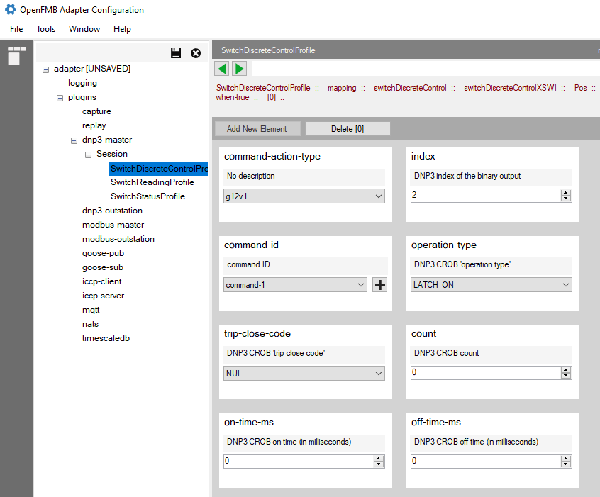
- On the right profile navigator tree, drill down to
- Assign MRID of the metering device to the profile by clicking on the
Configure NATS by expanding
pluginsand select NATS.- Make sure that the
enabledcheckbox is checked. - Enter NATS connection URL.
- Select
noneasSecurity Type. - Click on
Reset Subjectsto populate the publishing profiles.
- Make sure that the
Save your configuration by clicking the
Savebutton or simply CTRL+S.